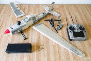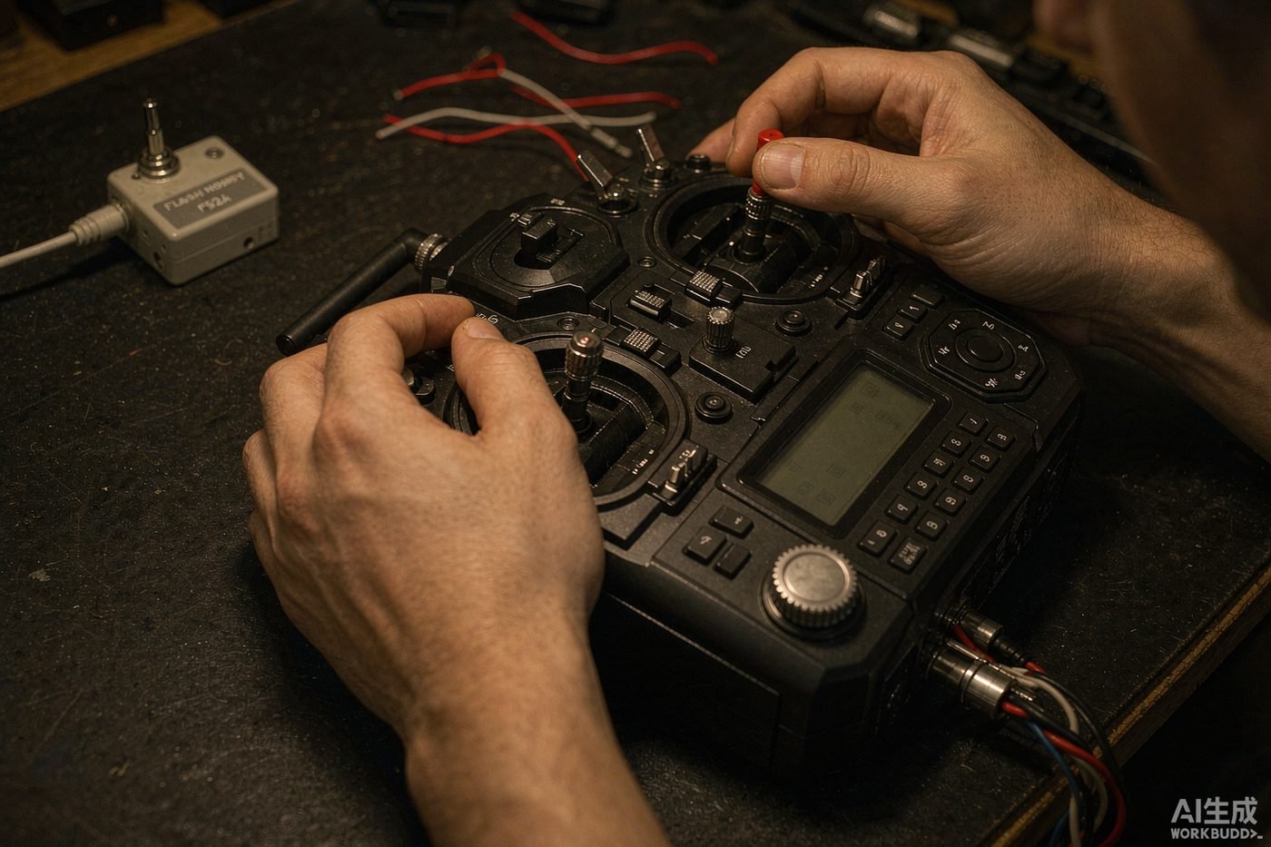

A badly set up transmitter makes a good model feel terrible, and a properly set up one makes an average model feel excellent. This is the sequence we run through on every new model before its first flight – it takes about ten minutes and it is the difference between a frustrating afternoon and a great one.
Before you start
You will need the model assembled with all linkages connected, a charged flight battery, and the manual’s recommended CG and control throws. Do the setup with the propeller removed or the motor disconnected – you will be moving surfaces near a spinning prop otherwise.
Step 1: Create a new model memory
Never configure a new aircraft over an existing model memory. Create a fresh one and name it. On the SkyPeak TX-8 you get 20 memories, so there is no reason to overwrite anything.
Set the correct wing type while you are here: normal (one aileron servo per wing) or elevon / V-tail if your model needs mixing. Getting this wrong is the most common reason a new model will not respond correctly.
Step 2: Bind the receiver
- Power the receiver using the bind plug fitted to its bind port (or hold the receiver’s bind button while powering it).
- Put the transmitter into bind mode – usually holding the bind button or menu item while switching on.
- Wait for the receiver LED to go from flashing to solid.
- Remove the bind plug, power everything down, then power the transmitter on first and the model second.
Step 3: Check and reverse your servos
Centre every stick and trim. Now work through each axis and confirm the surface moves the correct direction:
- Elevator back (pull) → elevator up
- Aileron right → right aileron up, left aileron down
- Rudder right → rudder right
- Throttle up → motor spins up
If a surface goes the wrong way, use servo reversing in the transmitter. Do not flip the servo arm or move the pushrod to a different hole – that changes your geometry and your throws, and you will chase the problem for the rest of the model’s life.
Step 4: Centre with sub-trim, then mechanically
If a surface does not sit exactly neutral with the stick centred, correct it in two stages. First use sub-trim to take up the remaining few degrees. If you need a large amount of sub-trim, stop – remove the servo arm, re-centre it by one spline, and start again. Large sub-trim values mean you have built the linkage slightly wrong, and electronic correction will give you uneven throws.
Step 5: Set endpoints and throws
Set the travel adjust (endpoints) so each surface reaches the deflection the manual recommends on high rate, without the servo buzzing or binding at full deflection. A servo that is mechanically stalled at full throw will drain your battery and can burn out.
A sensible starting point for a sport model:
| Surface | Low rate | High rate |
| Aileron | 10-12 mm | 16-20 mm |
| Elevator | 8-10 mm | 14-18 mm |
| Rudder | 20-25 mm | 35-45 mm |
| Flaps (if fitted) | 10 mm | 30-45 mm for landing |
Measure at the widest point of the control surface. Fly the first few flights on low rates.
Step 6: Add expo
Expo softens the response around centre stick without reducing maximum throw. It is the setting that makes a twitchy model feel smooth without making it unresponsive when you need full deflection.
A good starting point is 25-30% expo on aileron and elevator for a sport model, and a little less on rudder. On a 3D model you might run 40-50%.
Step 7: Set up dual rates on a switch
Put low and high rates on a two-position switch so you can change them in flight. Take off on low rates, and switch to high rates once you are comfortable and at altitude.
Step 8: Calibrate the ESC throttle range
With the propeller removed, power on with the throttle at full. The ESC should beep a confirmation, then move the throttle to zero. You will hear a second confirmation and then the normal cell-count beeps. This teaches the ESC your transmitter’s actual throttle endpoints – skip it and you can end up with a motor that will not start, or one that will not reach full power.
Step 9: Set a throttle cut
Assign throttle cut to a switch and use it every single time you approach the model. A throttle cut that kills the motor but leaves the surfaces live is the single best safety habit in this hobby.
Step 10: Range check
With the model secured and the motor disabled, walk 30-50 metres away with the transmitter in range-check mode (antenna not extended, if your radio specifies that) while someone confirms all surfaces still respond correctly. Do this before the first flight of every new model, and again after any crash.
Common problems
- Surfaces move but the motor will not start – throttle not calibrated, throttle reversed, or the throttle cut is engaged.
- One aileron moves the wrong way – wing type set to elevon, or the servo needs reversing.
- Model rolls or pitches on its own – trims not centred, or the gyro is fighting you. Check the stabiliser direction.
- Servo buzzes at full deflection – endpoint is beyond the mechanical limit. Reduce travel adjust.
Need a hand?
Most setup problems take us about two minutes to identify from a photo or a short video. Send us your model, radio and what you are seeing and we will talk you through it. More questions are answered in the FAQ.